|
|
|

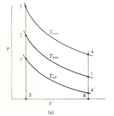
Figure 1(a): P-V Stirling cycle as cooling engine. The expansion process occurs at a temperature of Tref in cooling engine

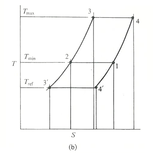
Figure 1(b): T-S Stirling cycle as cooling engine. The expansion process occurs at a temperature of Tref in cooling engine
The same ideal machine which was used to describe the operation of the Stirling cycle as a prime mover can be used to describe the operation of the cycle as a refrigerating machine. The only difference is that the temperature of the heat supplied from the external source during expansion is lower than the temperature at which heat is rejected from the working fluid during compression. This is illustrated in figure 1 where the P-V and T-S diagrams for the prime mover and refrigerating machine are superimposed. When the Stirling-cycle machine is operating as a refrigerator, heat is lifted from the cold zone during the expansion process 3'-4'. The work of compression (area 1-2-5-6) is the same for both the prime mover and refrigerator. The work of expansion (area 4'-3'-5-6) in the case of a refrigerator is less than the compression work and work equivalent to area 1-2-3'-4' from an external source is necessary to drive the cycle. During transfer from the compression space to the expansion space in process 2-3', the working fluid experience a decrease in temperature, and a corresponding increase in temperature during the alternate transfer process 4'-1.
The performance of a refrigerator is assessed in terms of its coefficient of performance (COP), where
The performance of a refrigerator is assessed in terms of its coefficient of performance (COP), where
COP= heat lifted/work done= Tref/(Tmin-Tref)