|
|
|

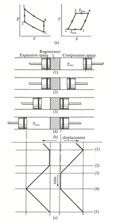
Fig.1: the Stirling cycle; (a) P-V and T-S diagrams; (b) piston arrangement at the terminal points of the cycle; (c) time-displacement diagram

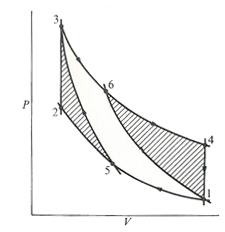
Fig. 2(a): Stirling and Carnot P-V cycle

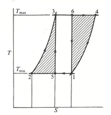
Fig. 2(b): Stirling and Carnot T-S cycle
The Stirling cycle is similar, in some respects, to the Carnot cycle, as illustrated in fig.1.
Consider a cylinder containing two opposed pistons, with a regenerator between the pistons. The regenerator (matrix of finely-divided metal) may be thought of as a thermodynamic sponge which alternatively releases and absorbs heat.
The volume between the regenerator and a piston maintained at high temperature Tmax is called the expansion space while the other, maintaned ad low temperature Tmin the compression space. As in the Carnot cycle, it is assumed that the pistons move without friction or leakage loss of the working fluid.
At the beginning, we assume that the compression-space piston is at the outer dead point and the expansion-space piston is at the inner dead point, close to the face of the regenerator. All the working fluid is then in the cold compression space. The volume is a maximun, so that the pressure and temperature are at their minimun values (point 1). During compression (process 1-2) the compression piston moves toward the inner dead point, and the expansion-space piston remains stationary. The working fluid is compressed in the compression space and the pressure increases. The temperature is maintaned constant because heat Qc is abstracted from the compression-space cylinder to the surrounds.
In the transfer process 2-3, both pistons move simultaneously, the compression piston towards (and the expansion piston away from) the regenerator, so that the volume between them remains constant. Therefore, the working fluid is transferred, through the regenerator matrix, from the compression space to the expansion one. In this passage through the regenerator, the working fluid is heated from Tmin to Tmax by the heat exchanged from the matrix. The temperature increase at constant volume, causes an increase in pressure.
In the expansion process 3-4, the expansion piston continues to move away from the regenerator towards the outer dead point; the compression piston remains stationary at the inner dead point, close to the regenerator. As the expansion proceeds, the pressure decreases as the volume increases. The temperature remains constant thanks to the heat Qe which is added to the system from an external source.
The final process in the cycle is the transfer process 4-1, during which both pistons move simultaneously, transferring the working fluid from the expansion space to the compression one. In the passage through the matrix, the working fluid releases heat and emerges at Tmin into the compression space.
Heat transferred in the process is contained in the matrix, for transfer to the gas in the process 2-3 of the subsequent cycle.
Therefore, the cycle is composed of four processes:
Process 1-2: isothermal compression at Tmin
Process 2-3: constant volume
Process 3-4: isothermal expansion at Tmax
Process 4-1: constant volume
If the heat transferred in the process 2-3 has the same magnitude as in process 4-1, then the only heat transfers between the engine and its sorroundings are (a) heat supply at Tmax and (b) heat rejection at Tmin. This heat supply and heat rejection at constant temperature satisfies the requirement of the second Law of Thermodynamics for maximum thermal efficiency, so that the efficiency of the Stirling cycle is the same as the Carnot cycle, i.e. eta=(Tmax-Tmin)/Tmax
A comparison of the P-V diagrams and T-S diagrams of a Carnot and Stirling cycle, between given limits of pressure, volume and temperature are shown in fig. 2a and 2b.